


Motorised DIY Camera Slider: How I Built a Compact Slide-and-Pan Slider with App-Based Control for Stunning Timelapses
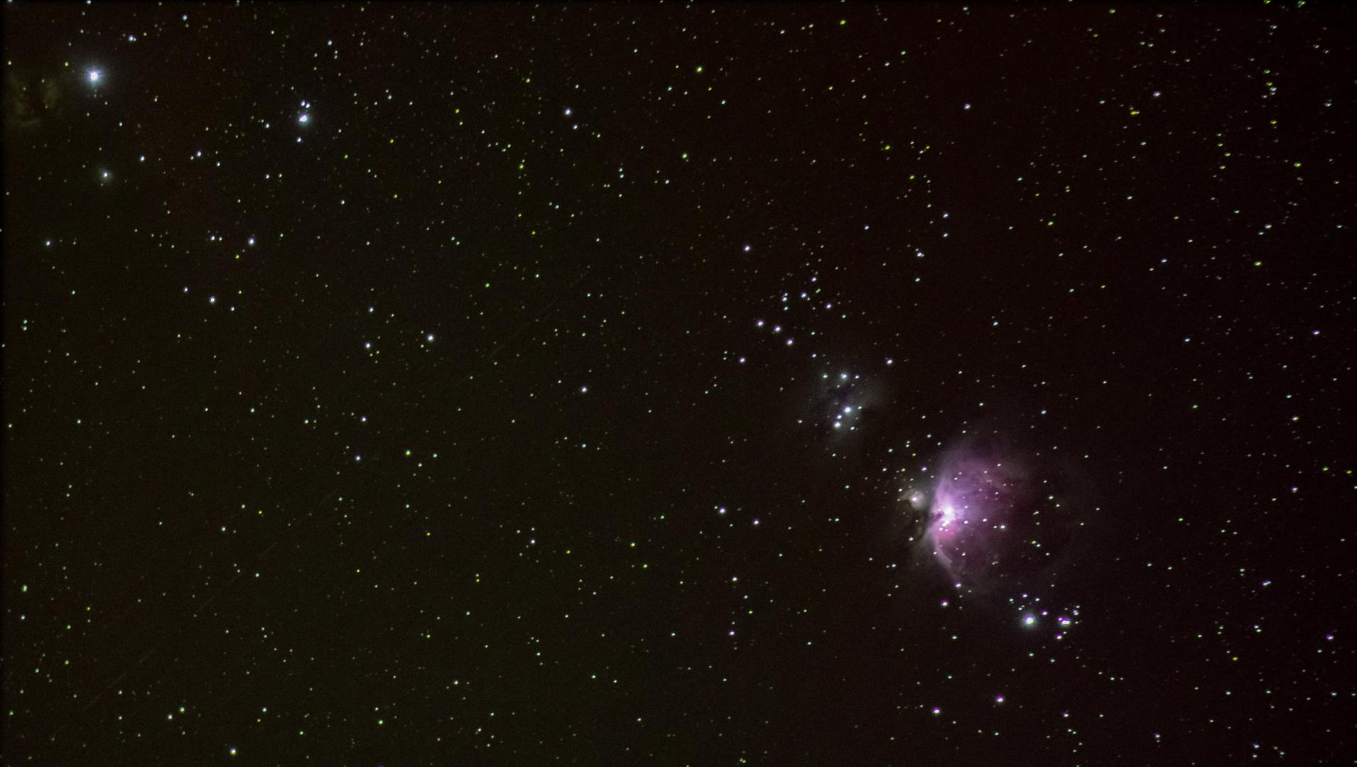
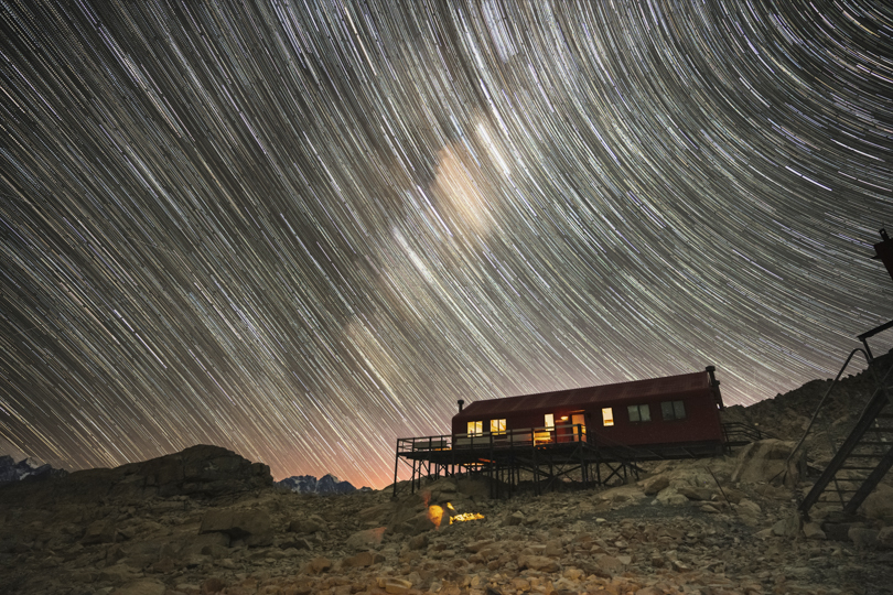
Timelapse videos are a fantastic way to capture and showcase dramatic changes in landscapes, weather, and lighting within just a few seconds. Creating the perfect timelapse, however, requires thoughtful preparation and attention to detail—a topic worthy of its own blog post. As you dive into the art of timelapse photography, you may encounter stunning examples featuring subtle movements, such as sliding or rotational effects, within the video. These dynamic elements not only elevate the visual appeal but also highlight the importance of incorporating motion to add depth and intrigue to your timelapse projects.
Thus, when aiming to create a stunning and captivating timelapse video, it quickly becomes clear that adding movement is essential. Recognizing this, many companies have developed products to meet this demand, offering a wide range of solutions. Brands like Edelkrone, Black Forest, and others provide impressive options, some of which are high-end systems designed for professional use. However, despite the variety, I’ve yet to find the perfect system that combines affordability, compactness, lightweight design, and all necessary features in one package. This challenge inspired me to start building my own system, exploring what’s possible and tailoring it to my specific needs.
Given my specific requirements, it was clear that the system needed to be compact and lightweight — ideally contained within a single housing that integrates all motors and control units. Additionally, it was crucial for the system to be easy to operate and set up, as patience tends to wane when working outdoors, especially in low-light conditions. With these considerations in mind, one can begin to envision a solution that balances practicality and performance.

Concept / Mechanics
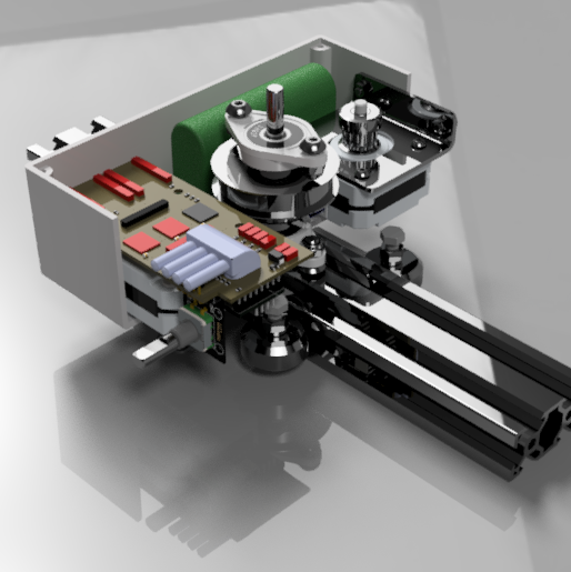
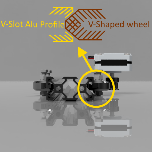
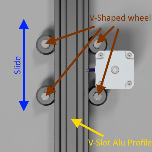
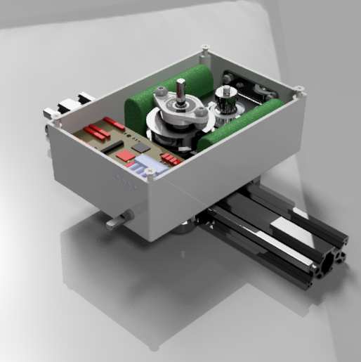
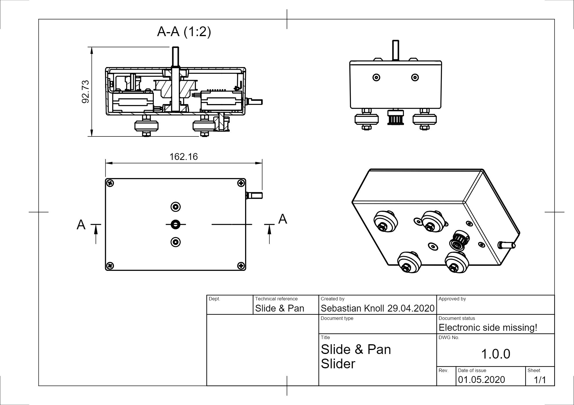
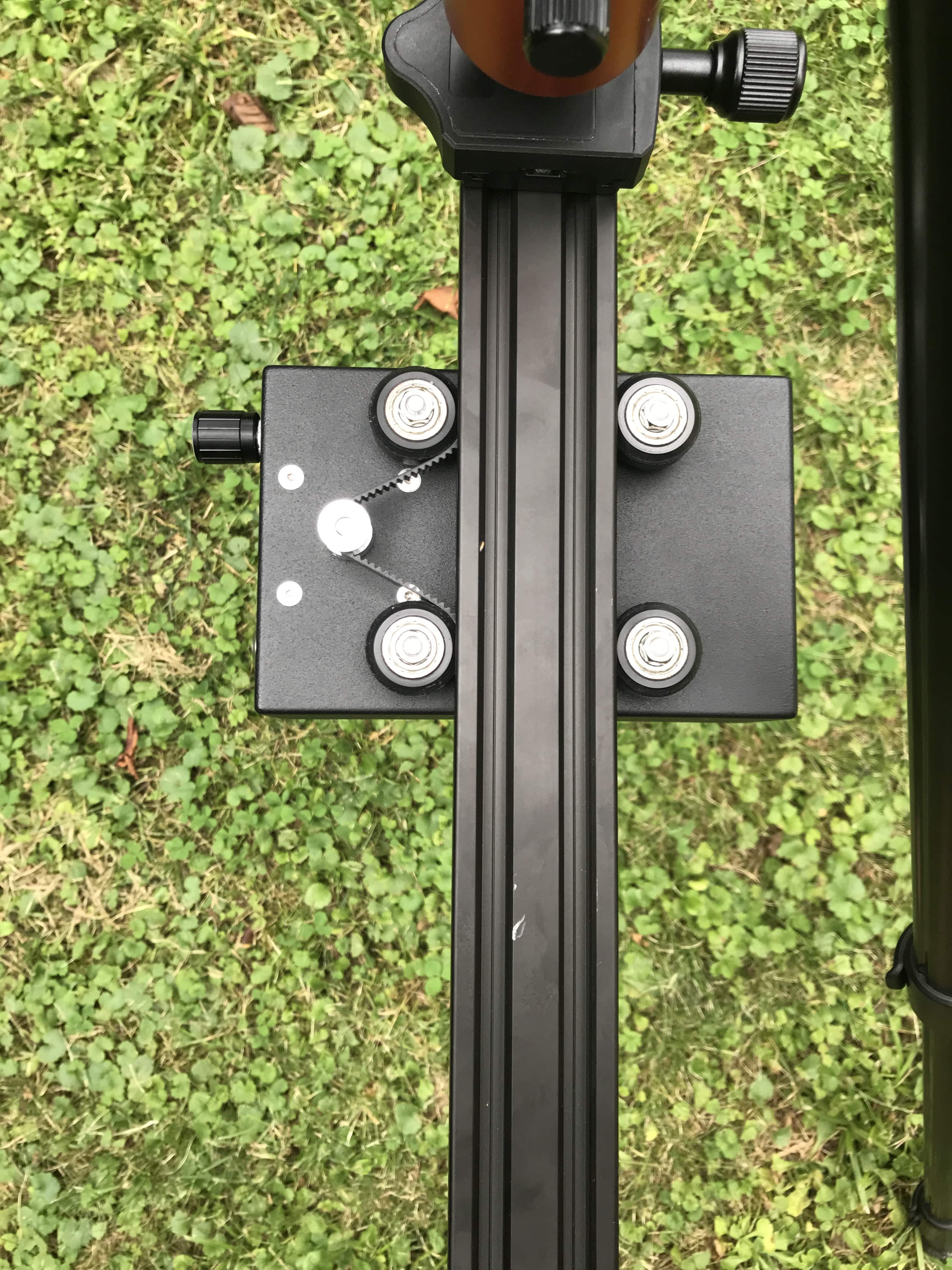
The goal was to achieve both a slide and pan movement for a relatively heavy camera system. Given that the camera and lens can be quite heavy, the system needed to be robust and properly dimensioned. I opted for a metal housing and sturdy rails and axes to ensure durability. To construct the sliding rails, I chose 20x40mm Aluminium V-Slot profiles, similar to the systems used in DIY 3D printers. The design includes four wheels attached to the cart or housing in such a way that the V-slot profile slides smoothly through them. Two wheels on each side fit into the V-slot, ensuring movement only in the desired direction. The V-slot profile and the V-shaped wheels also allow the system to operate upside down. For the pan axis, I added an additional aluminum axis to reduce stress on the motor’s axis and to introduce an extra gear ratio, which could be useful in certain situations.
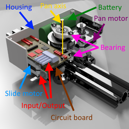
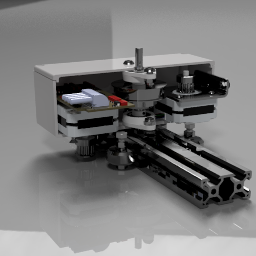
To enable the two movements, two independent motors are required. Given space and weight constraints, I chose small stepper motors with sufficient power to drive the system. The slide motor is positioned in such a way that its axis aligns with the V-Slot aluminum profile, allowing for the attachment of a pulley through which a timing belt can pass. As the slide motor rotates, the timing belt—fixed at both ends of the V-Slot profile—drives the sliding motion of the housing. On the opposite side, I placed another stepper motor for the pan movement. In this case, the motor axis is directed into the housing, and an attached pulley drives the additional axis via a timing belt. The entire mechanical setup is enclosed within the housing, not only for aesthetic reasons but also to securely mount the extra pan axis using bearings at both the top and bottom of the housing.

Once the motor and movement setup was defined, I focused on finding the right housing. The challenge was to accommodate not only the motors but also the electrical components, while keeping the overall size as compact as possible. An aluminum metal housing designed for electrical installations proved to be ideal. It offered the perfect dimensions and was made from durable material, allowing for the secure attachment of screws and wheels. The remaining space was then used to house the electrical hardware, including the circuit board, batteries, and various input/output peripherals.

After conceptualizing the mechanics and verifying the mechanical system on the computer, it was time to create the construction plans and order all the necessary parts. With the help of a friend, we prepared the components and assembled the first physical version of the system. The concept, which had only existed in theory, proved to be functional and practical in the real world, confirming its usability.
Hardware / Electronics
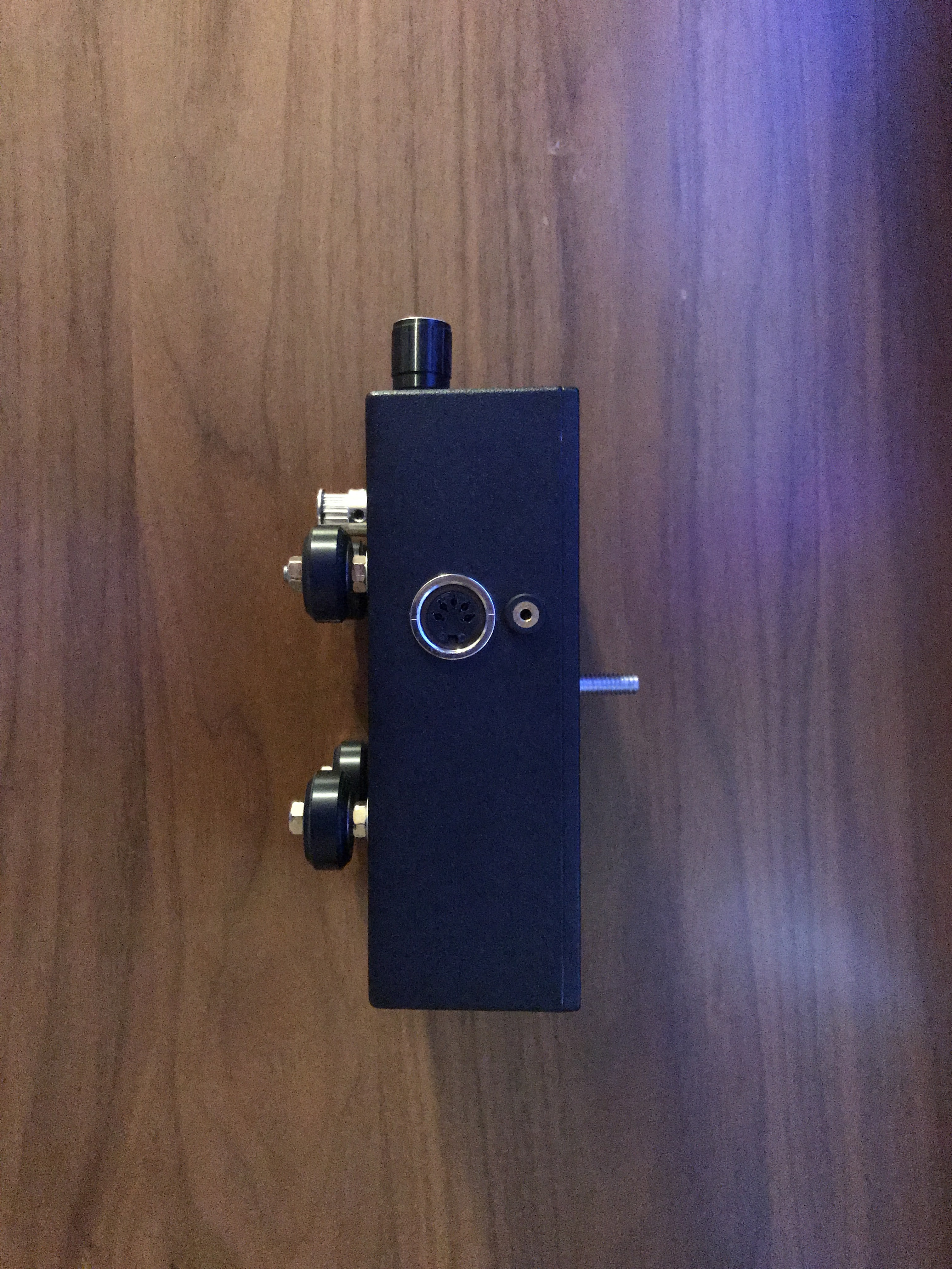
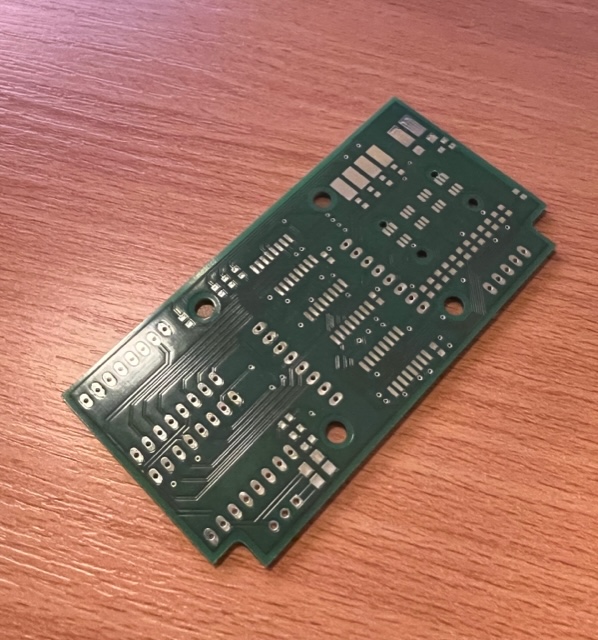
I developed the hardware and electronics in parallel with the mechanical system to ensure that the circuit board would fit within the housing and that the input/output peripherals would be appropriately placed. My goal was to integrate all the circuitry onto a single board to minimize wiring. The primary task was to position and connect the motor drivers, microcontroller, power supply, and input/output components. All elements were arranged on the circuit board and can be replaced easily through a simple socket system. For the microcontroller, I selected a Wemos D1 mini, which is a powerful board featuring an ESP8266 Wi-Fi controller. This allows the system to create its own Wi-Fi network for remote control, alongside the physical input elements. After designing the board and testing the system with manually wired connections, I ordered the circuit board and began inserting the components to afterwards refine the software.
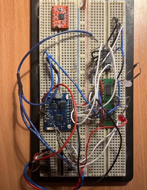

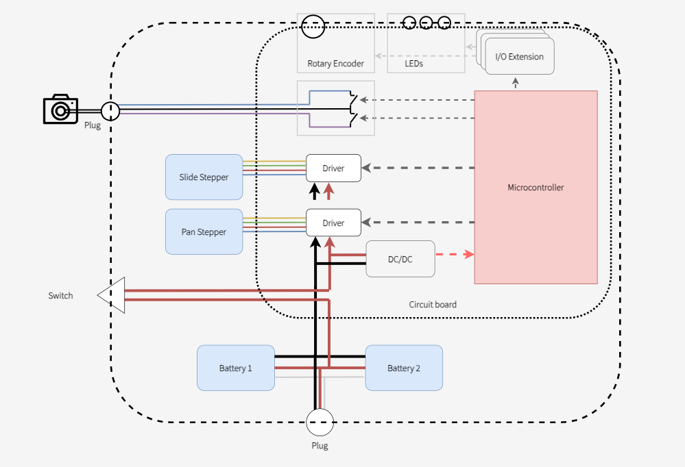
In detail, the circuit board connects the power supply to the stepper drivers and, through a DC/DC converter, to the microcontroller. The power supply is powered by two lithium-ion batteries, which can be disconnected via a switch and charged through an external port. The microcontroller’s relevant pins are then connected to the motor drivers and input/output peripherals. Due to running out of I/O pins, I added an I/O extension board to ensure the rotary encoder’s signals could be read and that the three RGB status LEDs could be controlled. Additionally, the electronics for triggering the camera's shutter had to be integrated, using a standardized system where optocouplers ensure the safety of the camera hardware.

Software
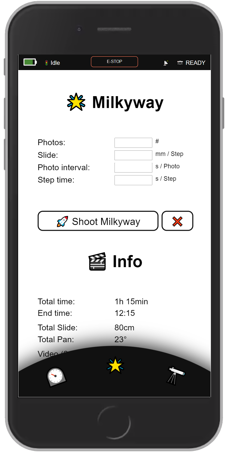
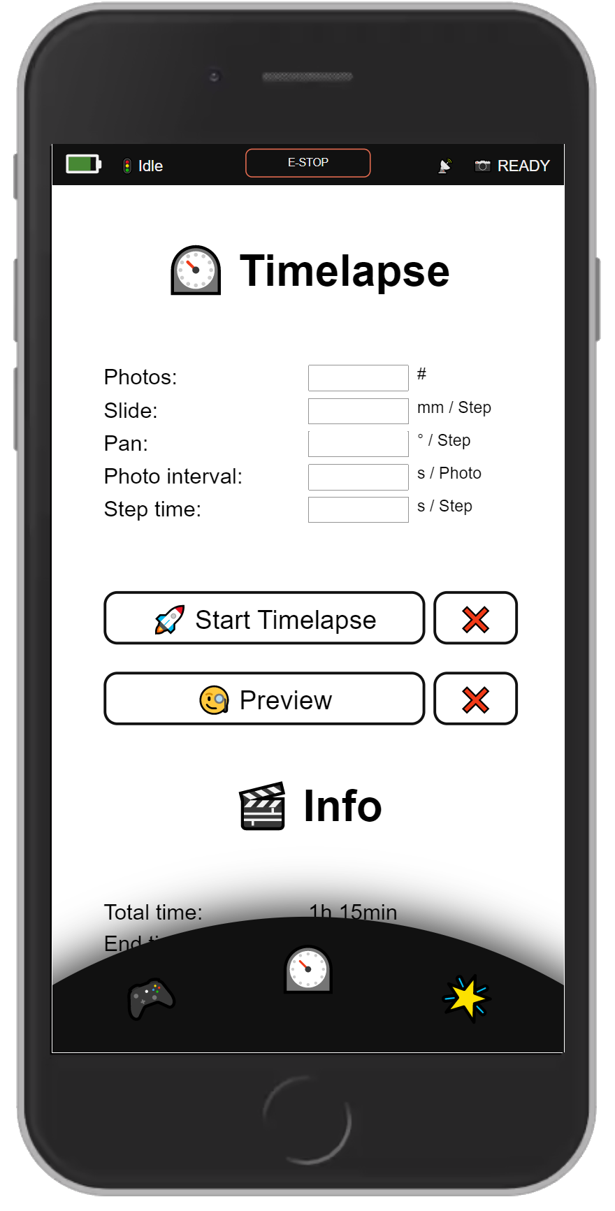
The software/firmware was developed in C++ using VS Code and the Platform.io extension. After implementing core functionalities like controlling the stepper motors (adjusting position, speed, and acceleration), reading the rotary encoder, and using the RGB LEDs to display various statuses, I then focused on creating several operation modes. These included manual control for sliding and panning, a Timelapse mode where users can define intervals, the number of photos, and the start/end positions of the slider, along with various other features. Users can select a mode via the rotary encoder, which, while not the most visually appealing option, is extremely practical for quick adjustments or when no phone is available. As an alternative, I programmed the system to create its own Wi-Fi hotspot, allowing users to connect with any Wi-Fi-enabled device and control the system through a web app, providing a much more intuitive and user-friendly experience.

GitHub / Open source
All implementation details, along with the construction plans, are available for free on GitHub. If you'd like to build your own system, feel free to use my work as a foundation and adapt it to your needs.
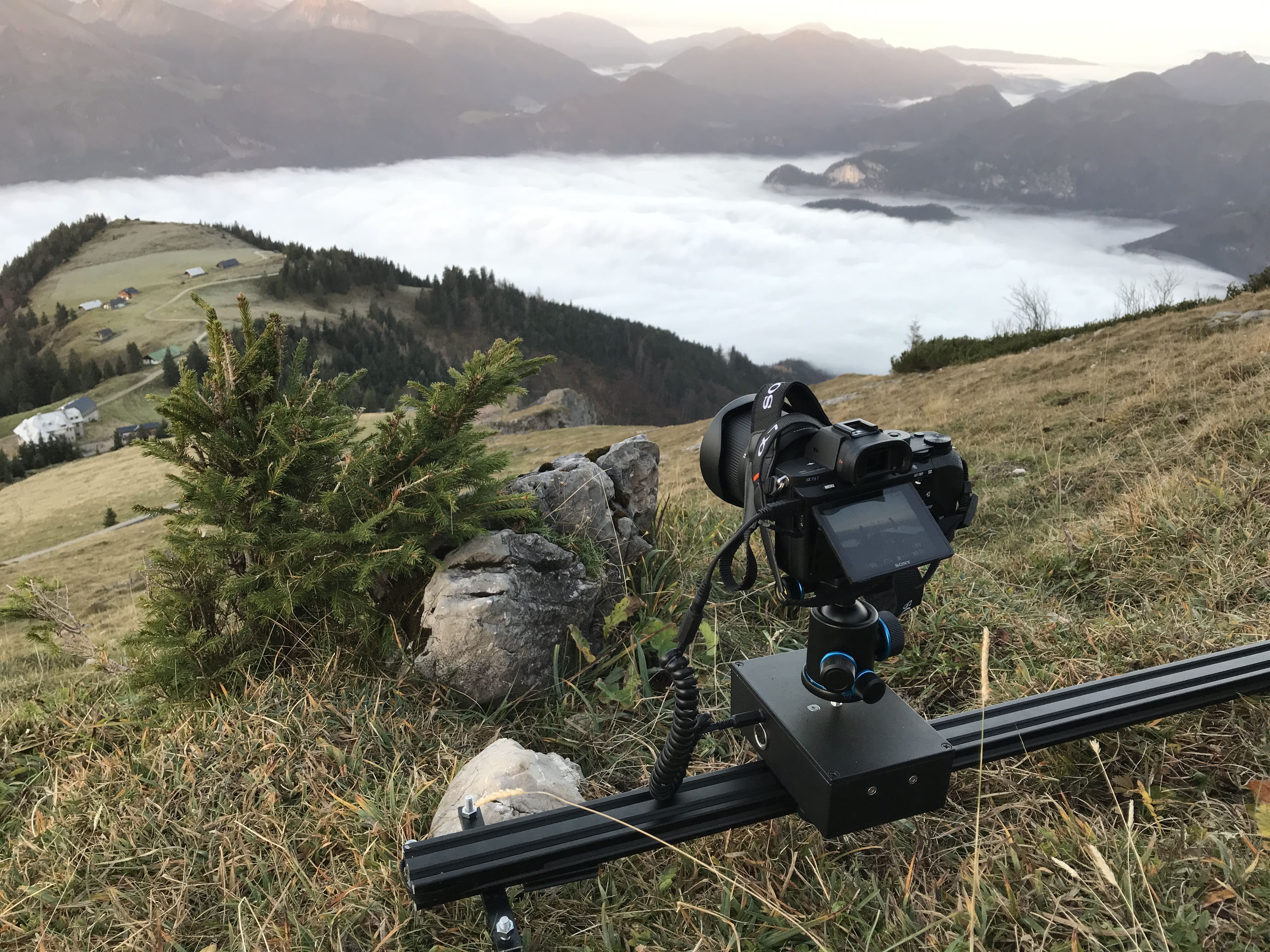
Result / Action
I am beyond satisfied with the final result. I successfully created an affordable slide-and-pan system for DSLR cameras that is compact, lightweight, and user-friendly. During several trips, I had the opportunity to test the slider and capture stunning timelapses featuring subtle movement and rotation. These elements added depth and intrigue to the final videos, making them far more captivating.
At the same time, I identified some drawbacks that I plan to address in the second version. One issue is that the pan axis is always fixed perpendicular to the sliding direction, allowing pan movements only when the sliding movement is straight. Otherwise, the camera rotates awkwardly. To fix this, I aim to make the pan axis adjustable relative to the sliding direction. Additionally, the choice of stepper motors needs reconsideration, as they consume a significant amount of power, even when stationary. To improve efficiency, I plan to replace them with geared DC motors, which only draw power during movement. This change could substantially extend the battery life from the current three hours to a much longer duration.
I’d love to hear your thoughts on this system and whether you’ve already found or built your ideal slide-and-pan solution!
Other DIY Slider systems
Since the internet is full of DIY camera sliders, I wanted to reference a few other projects that I find particularly impressive and/or that served as inspiration for my own build.
- How to Motorize a Camera Slider - Arduino based - Handy_Bear
- Make a Motorised Pan and Rotate Camera Slider - Arduino based - thediylife
- Arduino-based DIY camera slider - Curious Scientist
- DIY Camera Slider with Pan and Tilt Head - Arduino Based - Dejan
