
The hardware itself is not hard but should you have concerns doing it yourself feel free to use my design or parts of it...
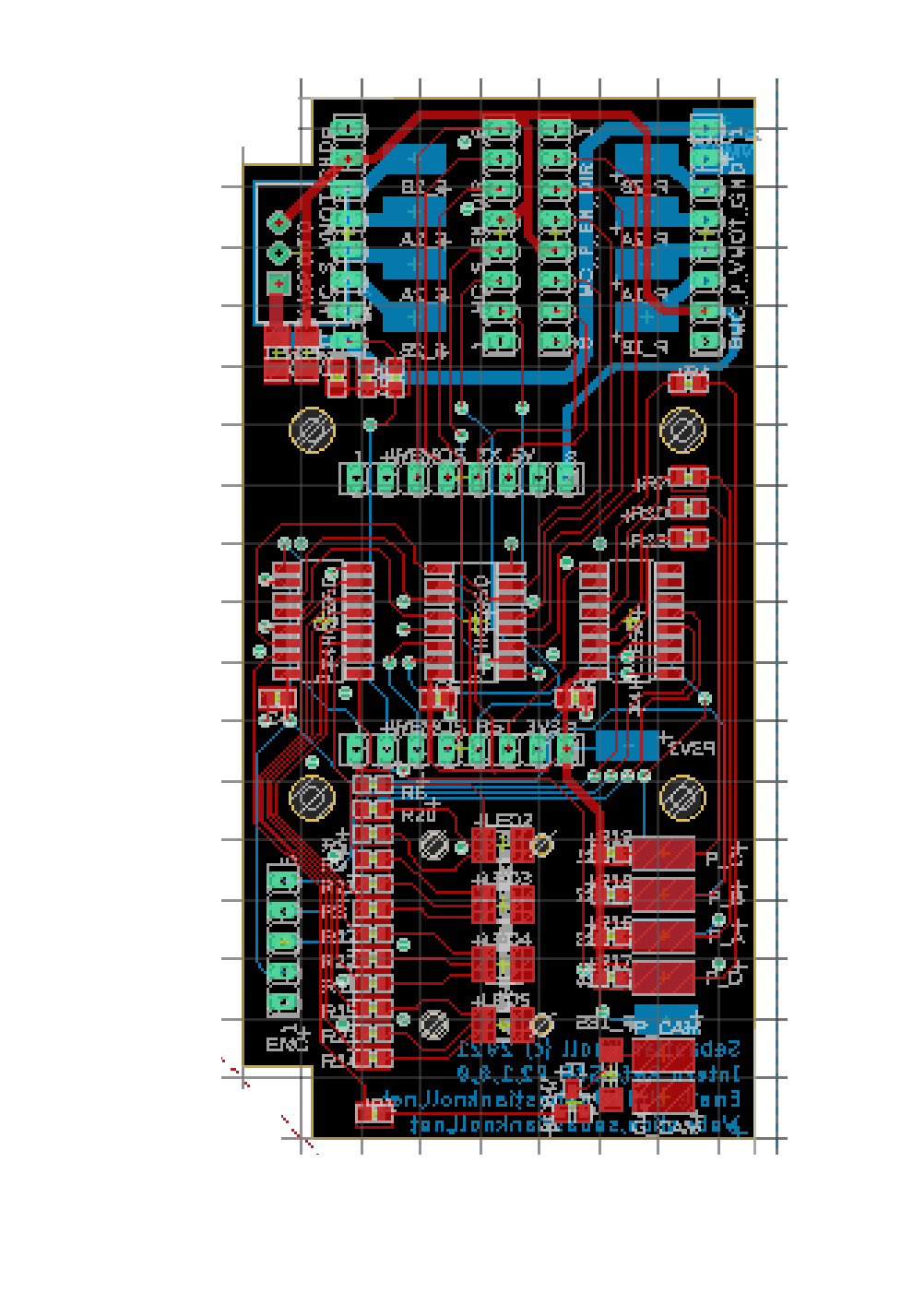
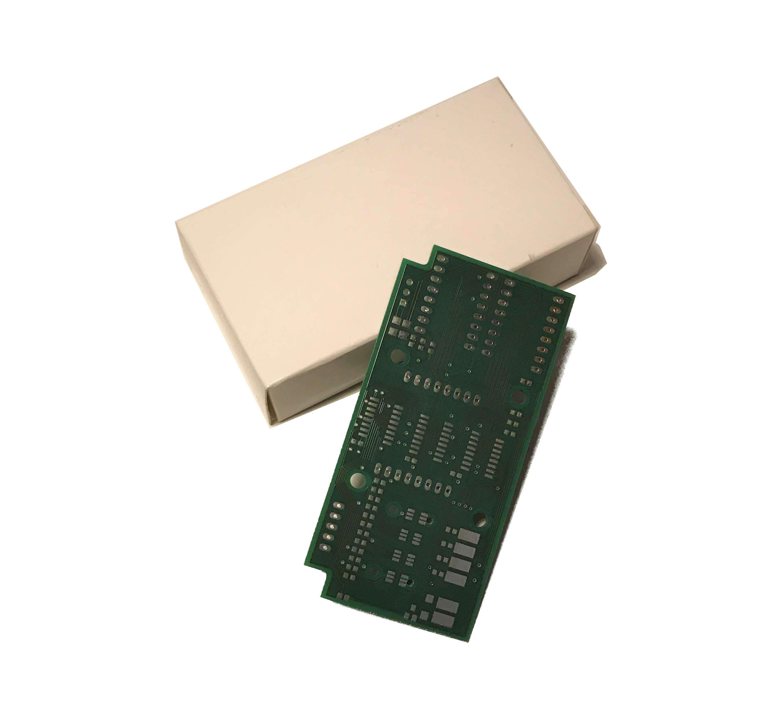
The hardware is quite an easy part since all parts are bought external and only have to be connected (in the right way of course). To do so and to save space one can design a circuit board that perfectly fits into the remaining place. For such a design Eagle (as a free program) comes quite handy and there are many companies where one can print/order the finished board. Besides that, soldering shouldn't be problem.
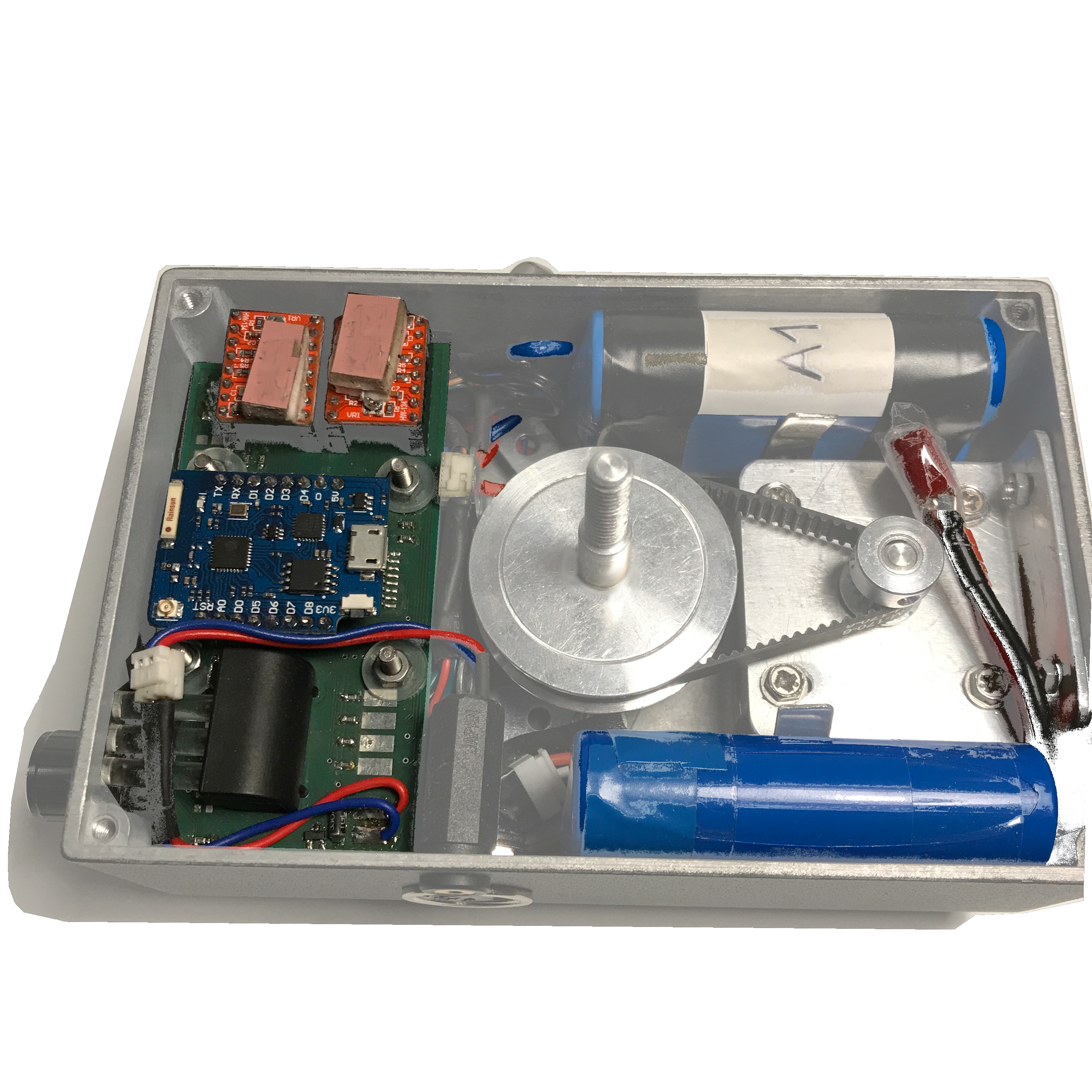
Whatever design you choose a power supply will be unavoidable. My suggested solution is two 7,4V LiPo batteries at the side next to the pan motor. The circuit for the power supply is straightforward by connecting the batteries in parallel (one might also connect the balancer in case of several cells) with a mentioned circuit board over a suitable switch. On the circuit board, a DC-DC-Converter within an appropriate input voltage range does the trick to overcoming the different voltages of the batteries. For charging the often enclosed chargers can be used whereby the connection is realized with an appropriate connection (eg. TODO).
Another unavoidable part is the pan and slide stepper and their driver. As for the power supply, the connection is straightforward and given by the used drivers. I suggest placing the drivers on the circuit board and use the power supply direct from the batteries (So the steppers have always the maximal possible voltage). With the driver on the circuit board it also possible to connect the control signals right away on the board.
The camera release (to trigger a photo and focus before) can be realized by connecting the camera with the normed cable, carry it into the slider with a plug, and connect the defined wires. The connection can be done with optocouplers or transistors actuated by the circuit board.
To give the user response of the current state and allow to make input a row of LED can be built-in. Thereby the LED state might be carried out with Light-Pipes. For input, a simple rotary encoder can be used.
Within the circuit board one can connect all necessary parts with the microcontroller. Extending the digital I/O with appropriate chips might get handy if you use an similar microcontroller with limited ports like I do (Wemos D1 Mini Pro).